Page jumps
- Introducing Verne
- e-Verne
- Verne in action
- Why “Verne”?
- Verne’s predecessors?
- e-Verne for Mac and Android and tablets and phones
Introducing Verne
Verne started out as a cardboard cut-out model that I developed for the Melbourne Gait Courses in 2009. He’s got the same number of segments as the conventional gait model and the joints are linked by papercraft eyelets. Little goniometers are printed on his hip, knee and ankle joints so you can orient Verne in any pose specified by the gait graphs. Alternatively you can put him in a particular pose and read off the joint angles. In the Courses we had a series of exercises to explore how the joints move during walking.
If you want to make a version then there is a .pdf file here that you can print out onto light card. Using proper papercraft eyelets works best. Brass paper fasteners are generally more easily available but don’t grip the joints the same way as the eyelets do and result in quite a lot of joint laxity! You can use them but the eyelets work much better.
e-Verne
Verne has now gone electronic (and become e-Verne) with the help of Flash animation (there are notes at the bottom of this page who want to use e-Verne from anything other than a Windows PC). The animation below allows you to interact with to explore the inter-relationships between the pose of the body segments and the joint angles. Using a mouse you can drag the segments to move e-Verne into whatever pose you want. If you hold down at the same time the next joint will be moved in such a way that the other segments preserve their original alignment. As you make movements the figures superimposed on the graphs record the position of the different joints.
The animation should open up in “Clearance” mode to allow you to investigate how the alignment of the segments affects clearance. The red arrow represents the ”vertical length” of the stance leg and the blue arrow that of the swing leg. The grey horizontal line represents hip height and the other horizontal line the lowest point on the foot. This will be green if the foot clears the ground and red otherwise.
Clicking the Step Length button sets “Step Length” mode. E-Verne will be depicted in a posture typical of the instant of foot contact. The distance by which the swing foot is in front of the stance foot at this instance will determine step length. The grey line represents normal step length. As you move the joints the other vertical line will represent whether you are obtaining an increased (green) or reduced (red) step length relative to this. Investigate the effect of stance phase knee flexion. You might be surprised to find out how big an effect this has on step length.
You can also click on the “Mass centres” button to toggle between displaying the centres of mass for each segment, each limb and that for the whole body.
Note: Verne may require an upgrade to Flash Player to work optimally on your computer and may not work at all on apple Macintosh machines.
Verne in Action
Here’s some photos of Verne being used to teach physiotherapy students at Centro Superior de Estudios Universitarios La Salle which is affiliated to Universidad Autónoma de Madrid. Be very happy to publish photos of Verne in different locations!

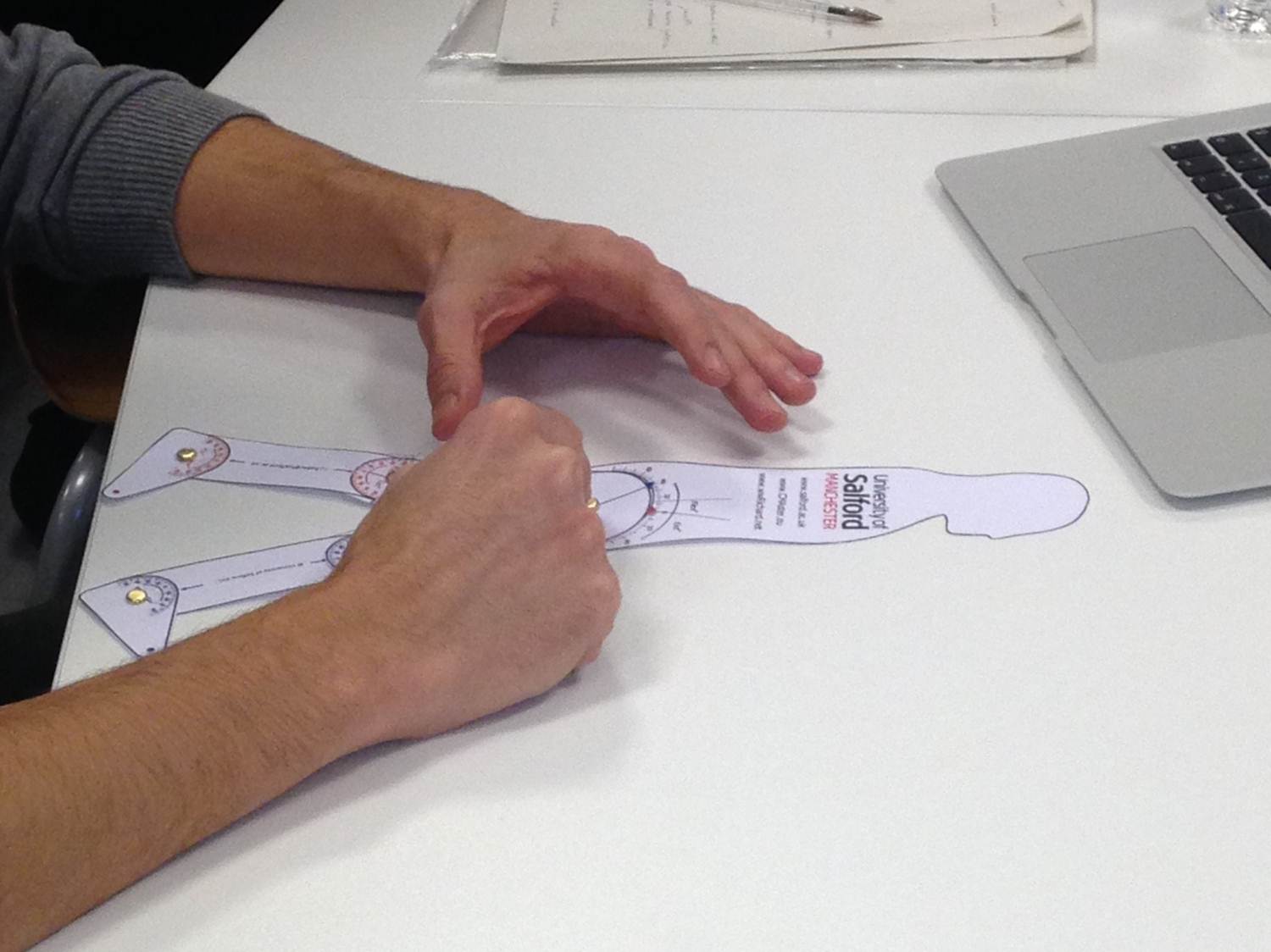
Photos courtesy of Sergio Lerma Lama.
Morgan Sangeux has used some rubber bands to create some muscles for Verne to help stimulate some discussion about how the physical exam relates to gait analysis.


Why “Verne”?
Verne is named after Verne T Inman the pioneering surgeon who established the Biomechanics Laboratory at the San Francisco campus of the University of California at Berkeley in the 1940s. In 1981 he published Human Walking with Frank Todd and Henry Ralston. The book is populated with wonderful drawings (too wonderful in some cases) simplifying the communication of biomechanical concepts. There are even a number of pictures of physical models he made or had made out of wood and hinges. I hope Verne can be seen as continuing in this tradition.
Verne T Inman (1905-1980)
Verne’s Predecessors
I was recently looking at the 1956 report of Wilfred Dempster which provides the data for body segment inertial parameters and in it I came across instructions for making a manikin very similar to Verne. This includes outline of segments for the cut out that are actually extremely similar to the ones in the .pdf file you can download above (see Figure below).

They were more interested in how cockpit and cabin spaces in vehicles could be designed to suit the operators and the the manikin was thus used to map out the space to which the operator could reach when seated and there’s actually a photo in the report (reproduced below) showing a version made out of aluminium.

One thing that has intrigued me for a long time is how many “new” ideas have been thought of before in movement analysis (and probably in life in general). This is a classic example.
More recently I’ve come across an even older example, however, from Braune and Fischer’s even earlier treatise “The Human Gait” which was originally released in chapter form between 1895 and 1904 (you can get a copy of the English translation from Amazon.co.uk if you have £1,000 to spare).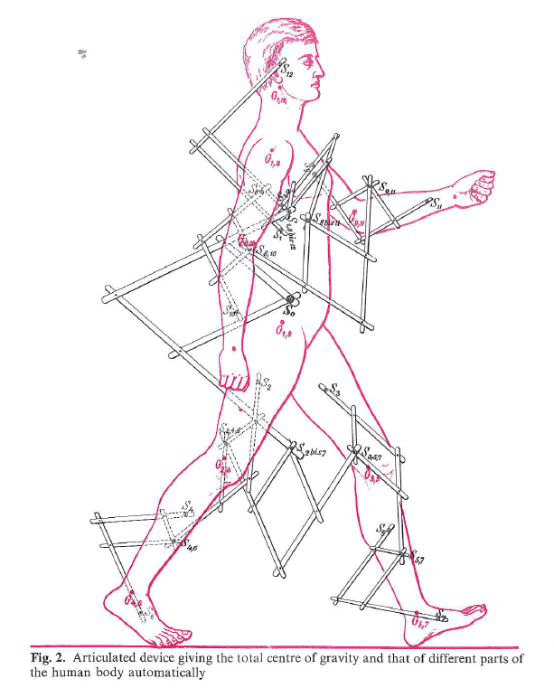
I scanned through the book and sure enough the image above is on page 127. The articulated scaffolding works in such a way that the black dot in the middle tells you were the centre of gravity is (maybe I’ll build that functionality into e-Verne some day).
Whilst checking to see if I could save myself the walk to the scanner by surfing to find if this image was already on-line I came across this one:
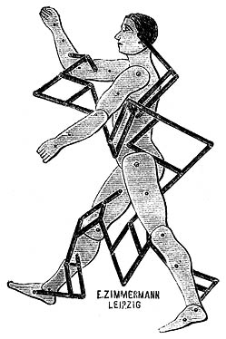
This is from the catalogue of the German scientific instrument maker Eduard Zimmermann published in 1904. It’s labelled as a “Schwerpunktmechanismus nach Fischer”. They obviously sold well because they are still listed in the 1928 catalogue where a fuller description is available. It doesn’t say how big this is but it weighed 4.6 kg so can’t have been small!
e-Verne for Mac and Android and tablets and phones
e-Verne is a Flash animation and it may require a little work to get him working on a Mac or Android machines (or Windows tablets). This will depend on the device, operating system and browser. Start off by just going to this link and seeing if it works: https://db.tt/Ny6wdfJP.
It should work in Google’s Chrome browser on both PCs and Macs but the mobile version of Chrome does not support Flash (see the Chrome support for further details). e-Verne certainly doesn’t work on my Android phone using Chrome but it will run using the Dolphin browser which you can install for free from the Google Play store. It is also available for iPads and iPhones which I assume you get from iTunes.
Mice and fingers
Verne was originally designed to be used with a mouse in which case you need to left click on a segment and drag whilst holding the left button down. This is undoubtedly the easiest way to drive him. Unfortunately many tablets and phones don’t allow you to do the same thing with your finger. You will probably still be able to tap on the segments to move them. If you tap on the anterior part of the segment the joint will move one way and if you tap on the posterior segment it will move the other way but this is clunky and difficult to control.
As an alternative if you tap on one of the graphs you should see the border changes colour to red (then blue then back to black) and some additional buttons appear on the top left of the main pane. Tapping on these will increase or decreased the joint angle you have selected in increments of 1° or 10°. To choose a different joint then just tap on another graph (and keep tapping until it turns the right colour). Using a mouse still works much better but you’ll find you can have a reasonable stab at the exercises this way.
Verne is very small on many phones – but that’s not his fault!

Hello, thanks for all the information. I just want to ask if is possible to fix the “e-Verne”, it’s not possible to see it. Thanks!
Hi great rreading your blog